Notice: I've enhanced the Real Fluid Heat Exchanger Solver since this web page was created, but have not yet had the time to update this web page to use that new solver. Therefor, this web page is being maintained mostly as a historical reference. If you would like more accurate and robust results, please consult Chapter 2 Section 3.3, Chapter 5, Appendix A, and Appendix B of my doctoral dissertation, A Study of Power Cycles Using Supercritical Carbon Dioxide as the Working Fluid, or install the Real Fluid Heat Engine Cycle Analysis Code on your computer and run the PlotSomeHeatExchangers.py script for yourself.
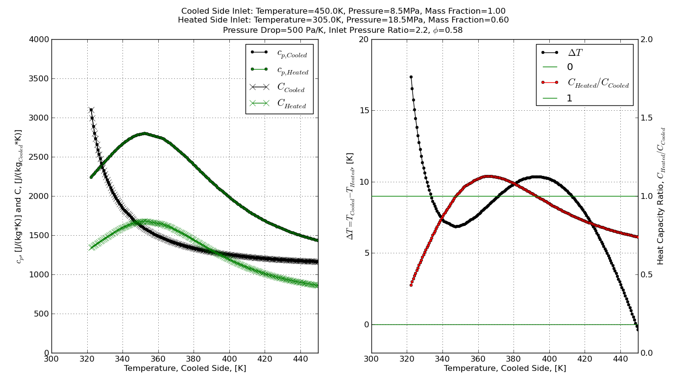
A zero dimensional real fluid heat exchanger solver has been developed as part of the Real Fluid Heat Engine Cycle Analysis Code. A separate interface is provided on this page to the heat exchanger solver, which plots specific heats, temperature, and temperature difference for the heated and cooled fluid streams in a heat exchanger. For more information about the methodology that this tool uses, see Section 3.3 of the document Mapping the Design Space of a Recuperated, Recompression, Precompression Supercritical Carbon Dioxide Power Cycle with Intercooling, Improved Regeneration, and Reheat.
Choose the inlet conditions for the heated and cooled fluids streams, as well as a pressure drop. The units for the pressure drop are Pascals/K. The mass flow rate of the heated and cooled fluid streams may be different. You may choose the flow rate of the heated fluid stream as a fraction of the flow rate of the cooled fluid stream. The solver is currently limited to carbon dioxide above the critical temperature (304.1282 K) for the working fluids and a common pressure drop on both the heated and cooled fluid streams. The solver will take several seconds to compute and the image will update automatically. Please be patient after your selection is made.
Notes:
- Some solutions, particularly where there is a small temperature difference near the critical point, may appear incorrect and have a slightly negative temperature difference. These issues are still being investigated.
- Cooled Side Inlet Temperature must be greater than the Heated Side Inlet Temperature. An error message will be presented if the Cooled Side Inlet Temperature is less than the Heated Side Inlet Temperature
- There are some additional cases which will fail with an error message, which is due to problems with the present technique and the fluid property database which is currently being used. These issues are still being investigated.
|