Overview
The energy seller's Distributed Charge Board A0 connects to the Tesla Gen2 Wall Connector to control it and communicate with the energy buyer's payment module inside the car through the charge cable. The power supply inside also powers the energy seller's Distributed Charge payment module. Below are instructions for making the required electrical connections. More information on the communication and mechanical packaging of the Distributed Charge Payment Modules can be found in the How It Works and Weatherproof Enclosure pages.
Notes
- Only the Tesla Gen2 Wall Connector works. The Tesla Gen3 Wall Connector will not. No other EVSE/wall unit/charge controller will work either.
- A CAT5 wire is used between the Tesla Gen2 Wall Connector and Distributed Charge Board A0 because it is a common, readily available cable type. The power and ground wires are doubled up because there are 2 extra wires in the cable.
- This document shows the single phase version. The 3 phase versions is similar, but has more phases and smaller AC power wires. The communication wires we are connecting to Board A0 will have the same termination points.
- Sourcing DC power from the wall connector eliminates the need for a separate power supply for the Distributed Charge Payment Module, but it does require a special Power Breakout Ribbon Cable.
Instructions
Tesla Gen2 Wall Connector Side
- Turn off the circuit breaker powering the Tesla Gen2 Wall Connector.
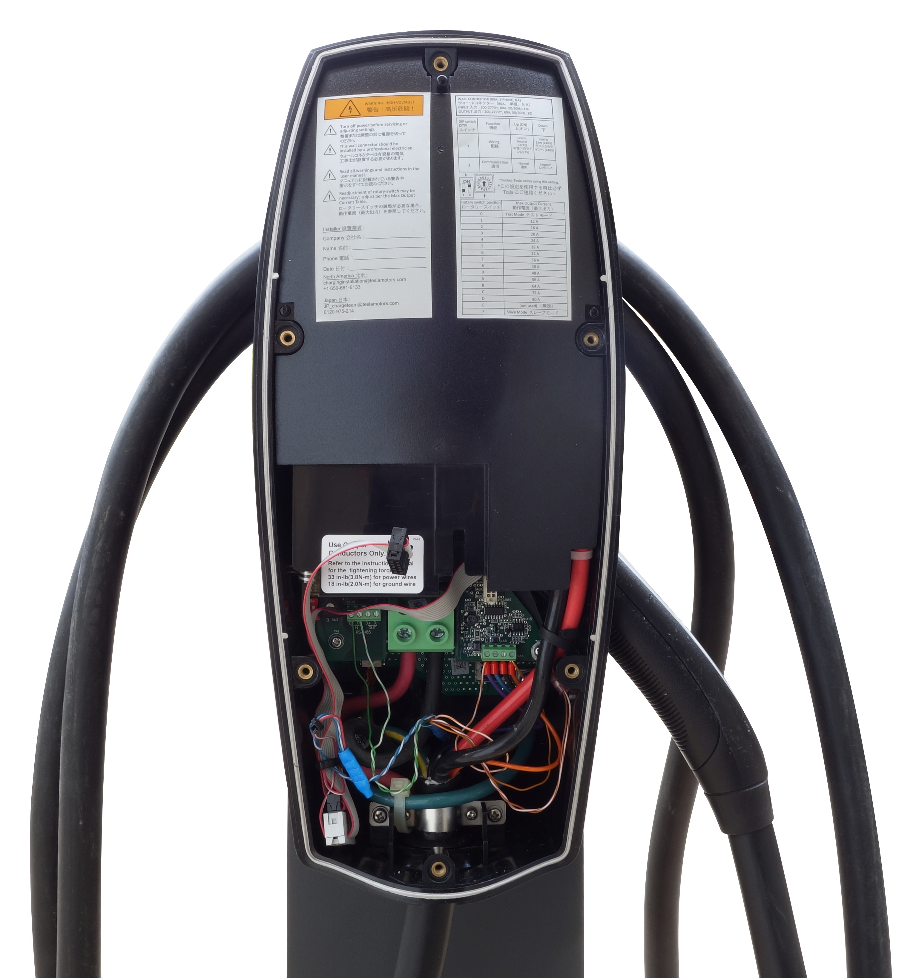
- Remove the cosmetic cover plate (not shown) by removing the 1 screw on the bottom and then snap it off. After the cosmetic cover plate has been removed, there are 6 screws that need to be removed to take off the weatherproof cover plate. Figure 1 shows the weatherproof cover plate already removed and Figure 6 shows the inside of the cover plate after it has been removed.
- Route a CAT5 cable from the Distributed Charge Payment Module to the Tesla Gen2 Wall Connector. The CAT5 cable should enter in the same rubber grommet as the AC power cables.
- Cut back the jacket and separate the wire pairs. Untwist the Orange+Orange/White pair. Strip the insulation back on all wires.
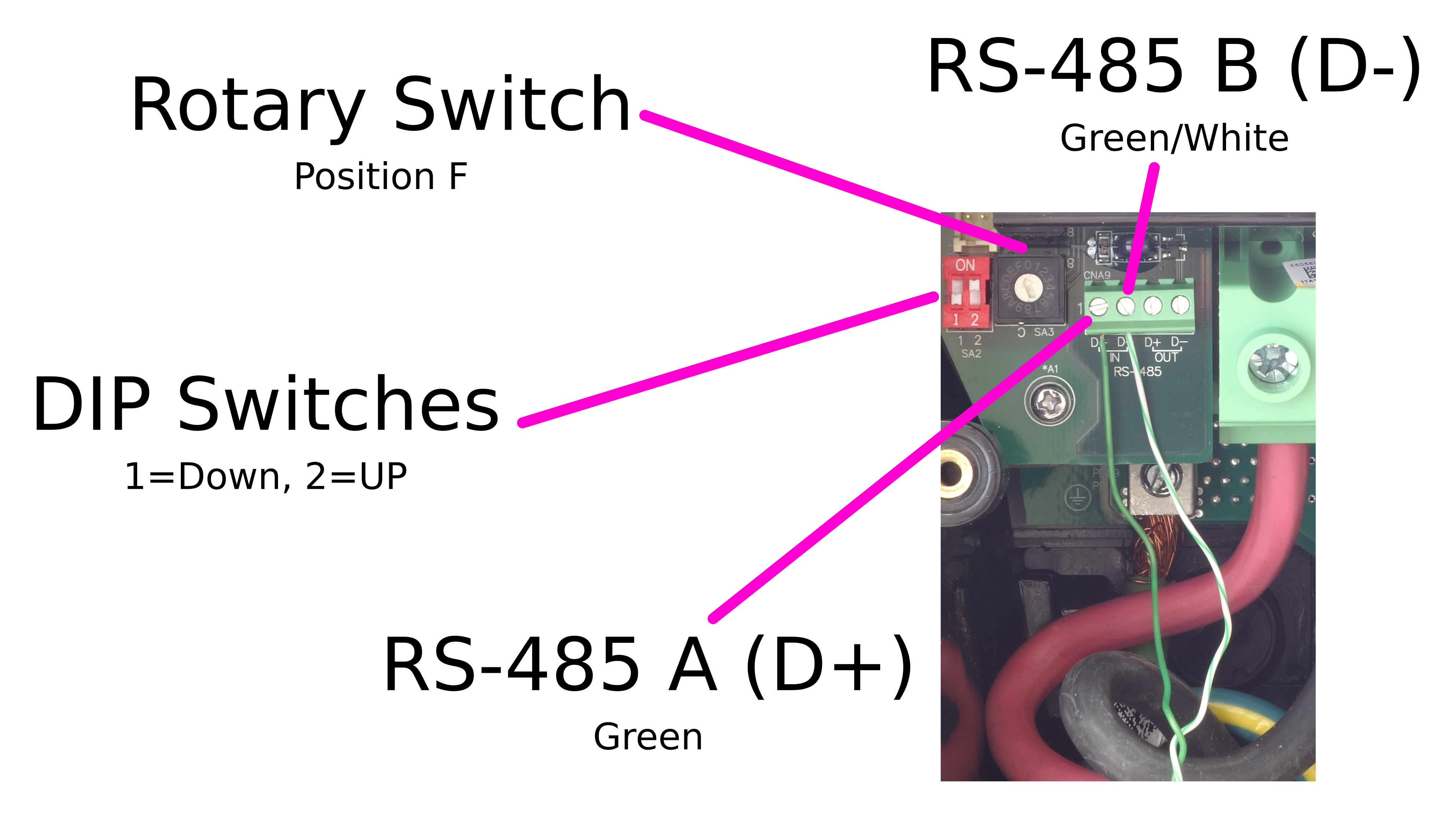
- Connect the Green+Green/White RS-485 wire pair on connector CNA9 as shown in the Figures below.
- Note: The RS-485 IN terminals are used. RS-485 OUT terminals are not used. The RS-485 wire pair should remain twisted as close to the connection as possible.
- Leave DIP switches 1 & 2 (SA2) unchanged.
- Note: The default position for DIP switch 1 is DOWN and DIP switch 2 is UP.
- The rotary switch (SA3) must be on position F in order to allow for control using the RS-485 connection.
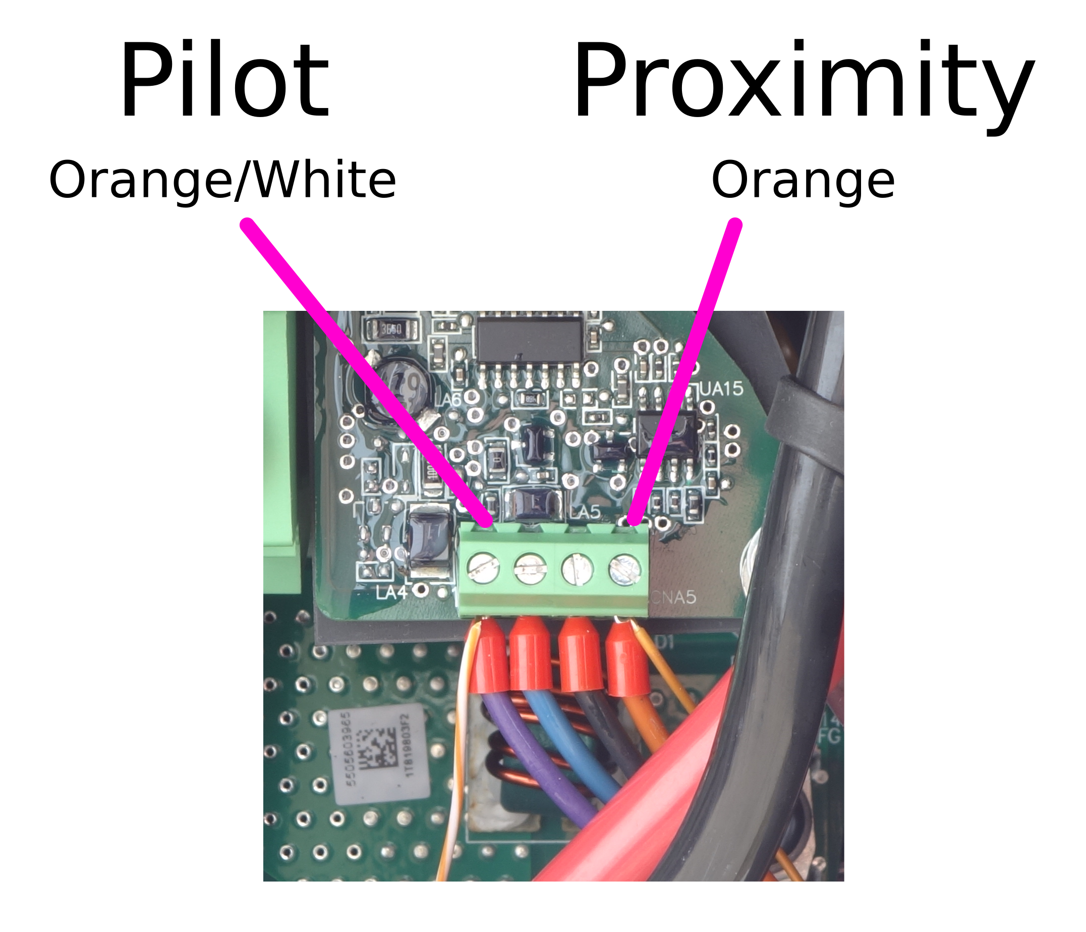
- Connect the Orange/White wire to the Pilot terminal on connector CNA5 as shown in the Figures below.
- Note: The existing purple wire comes from the charge cable.
- Connect the Orange wire to the Proximity terminal on connector CNA5 as shown in the Figures below.
- Note: The existing orange wire comes from the charge cable.
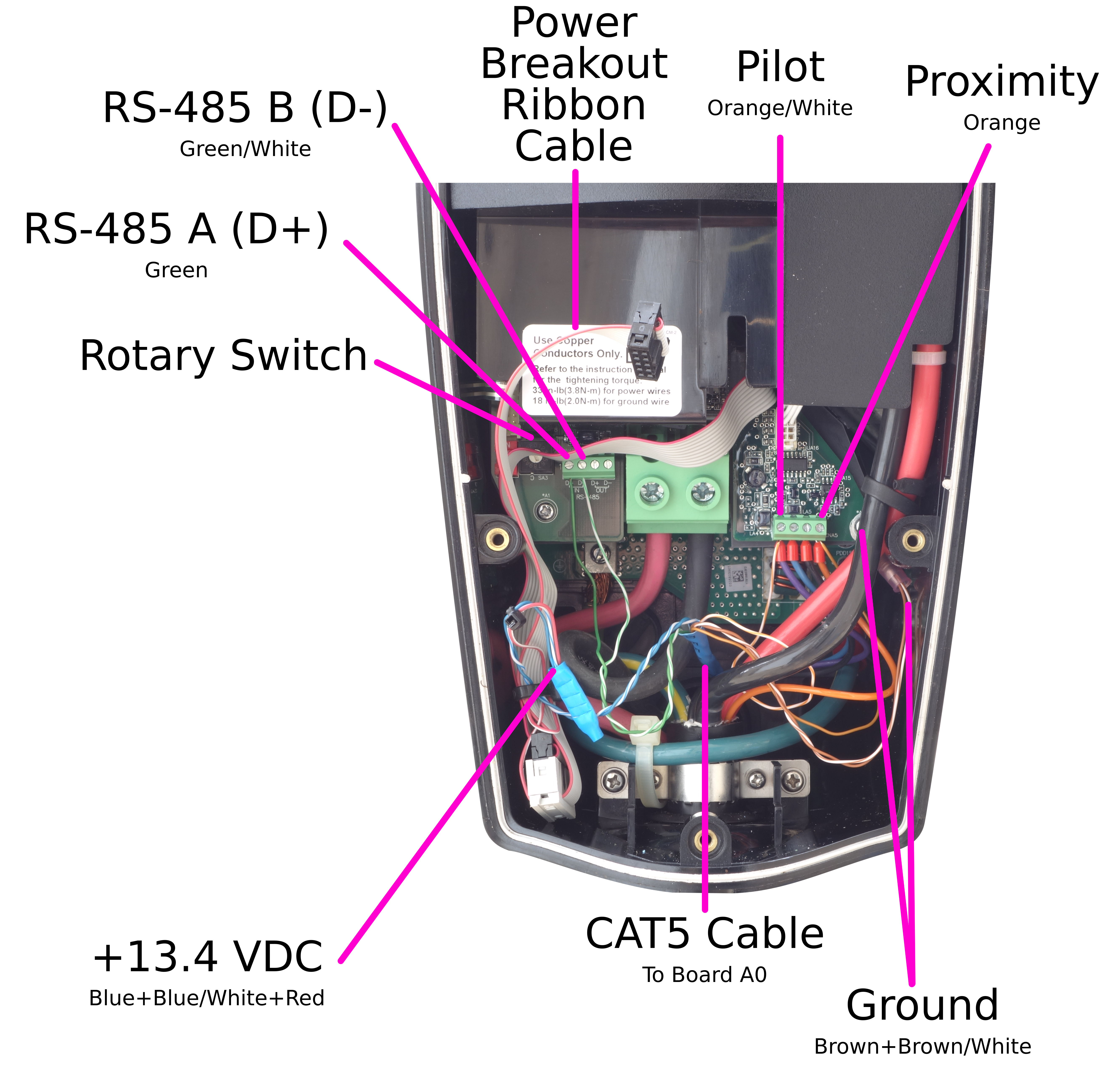
- The Brown+Brown/White wire pair is used for ground. The pair needs to be crimped to a ring terminal connector. There is a phillips screw that needs to be removed behind the red and black AC power lines that are coming from the charge cable. This is shown in Figure 2, but it is hard to see. After removing the screw, insert the ground ring terminal and reinstall it.
- The Power Breakout Ribbon Cable shown in Figure 2 & 5 is provided to source power from the +13.4VDC wire in the ribbon cable that normally only goes to the LEDs on the weatherproof cover plate. The Blue+Blue/White wire pair in the CAT5 cable needs to be attached to the red wire coming from the Power Breakout Ribbon Cable using a crimp connector. This is shown in Figure 2 in the lower left corner of the wall connector using a blue crimp connector. After crimping together, plug the white end into ribbon cable that normally goes to the LEDs on the weatherproof cover plate as is seen in the lower left corner of the wall connector in Figure 2. It is recommended to also use a zip tie to hold the excess wire together. This will avoid the risk of the plug coming loose or damaging the thin red power wire. Next, plug the black end into the ribbon cable connector on the inside of the weatherproof cover plate (shown in Figure 6) and then reinstall the cover plate.
Distributed Charge Payment Module Side
- You should have the door of the Distributed Charge Payment Module's Weatherproof Enclosure opened and a CAT5 cable routed from the Tesla Gen2 Wall Connector.
- Cut back the jacket and separate the wire pairs. Untwist the Orange+Orange/White pair. Strip the insulation back on all wires.
- On the screw terminals of the black connector shown in Figure 7 & 8 below, connect the
- Green+Green/White RS-485 wire pair,
- Orange/White Pilot wire,
- Orange Proximity wire,
- Brown+Brown/White Ground wire pair, and
- Blue+Blue/White +13.4 VDC wire pair.
- Close the door of the Distributed Charge Payment Module's Weatherproof Enclosure.
- Turn back on the circuit breaker powering the Tesla Gen2 Wall Connector.
Figures
|
Figure 1: Tesla Gen2 Wall Connector (Front Cover Removed)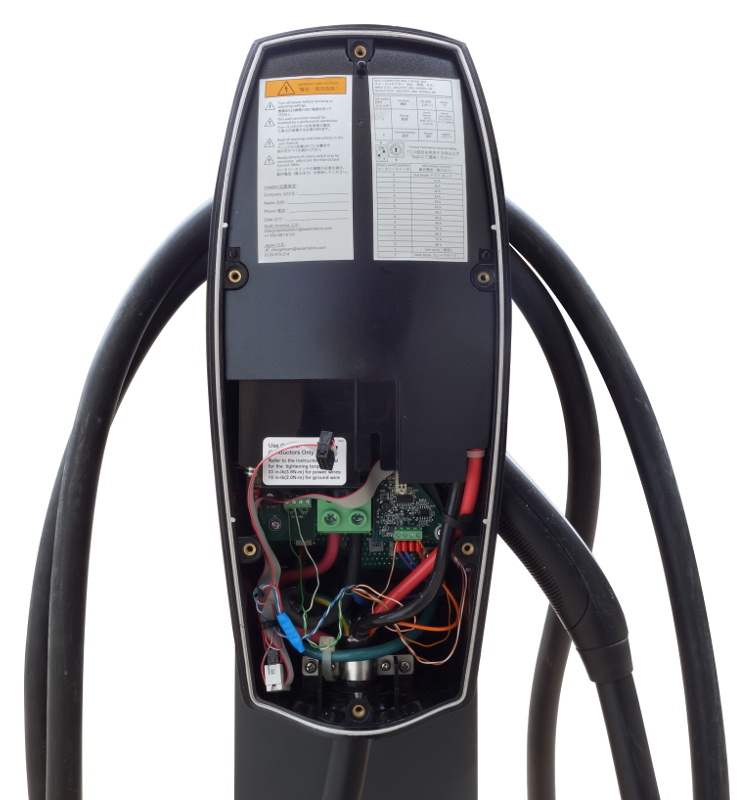
Figure 2: Overview Of Electrical Connections To Distributed Charge Board A0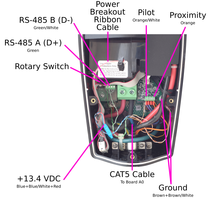
Figure 3: Detail Of The Pilot And Proximity Electrical Connections To Distributed Charge Board A0
Figure 4: Detail Of The Rotary Switch, DIP Switches, And RS-485 Connections To Distributed Charge Board A0
Figure 5: Power Breakout Ribbon Cable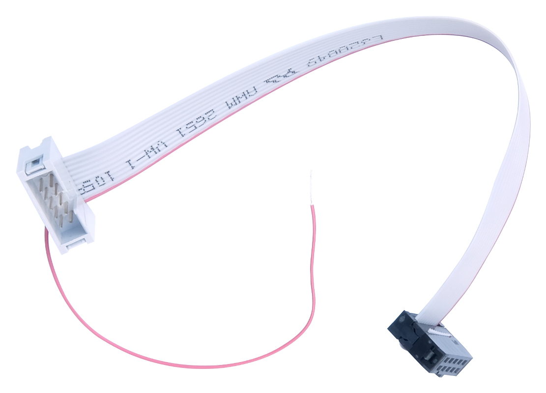
Figure 6: Weatherproof Cover Inside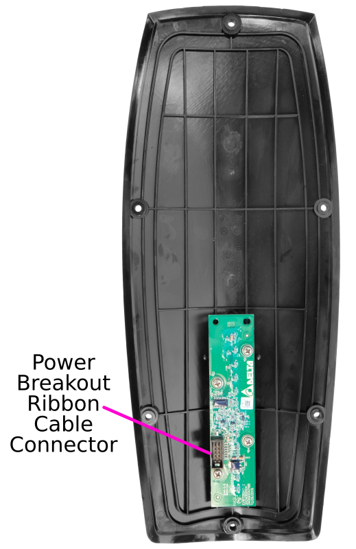
Figure 7: Distributed Charge Board A0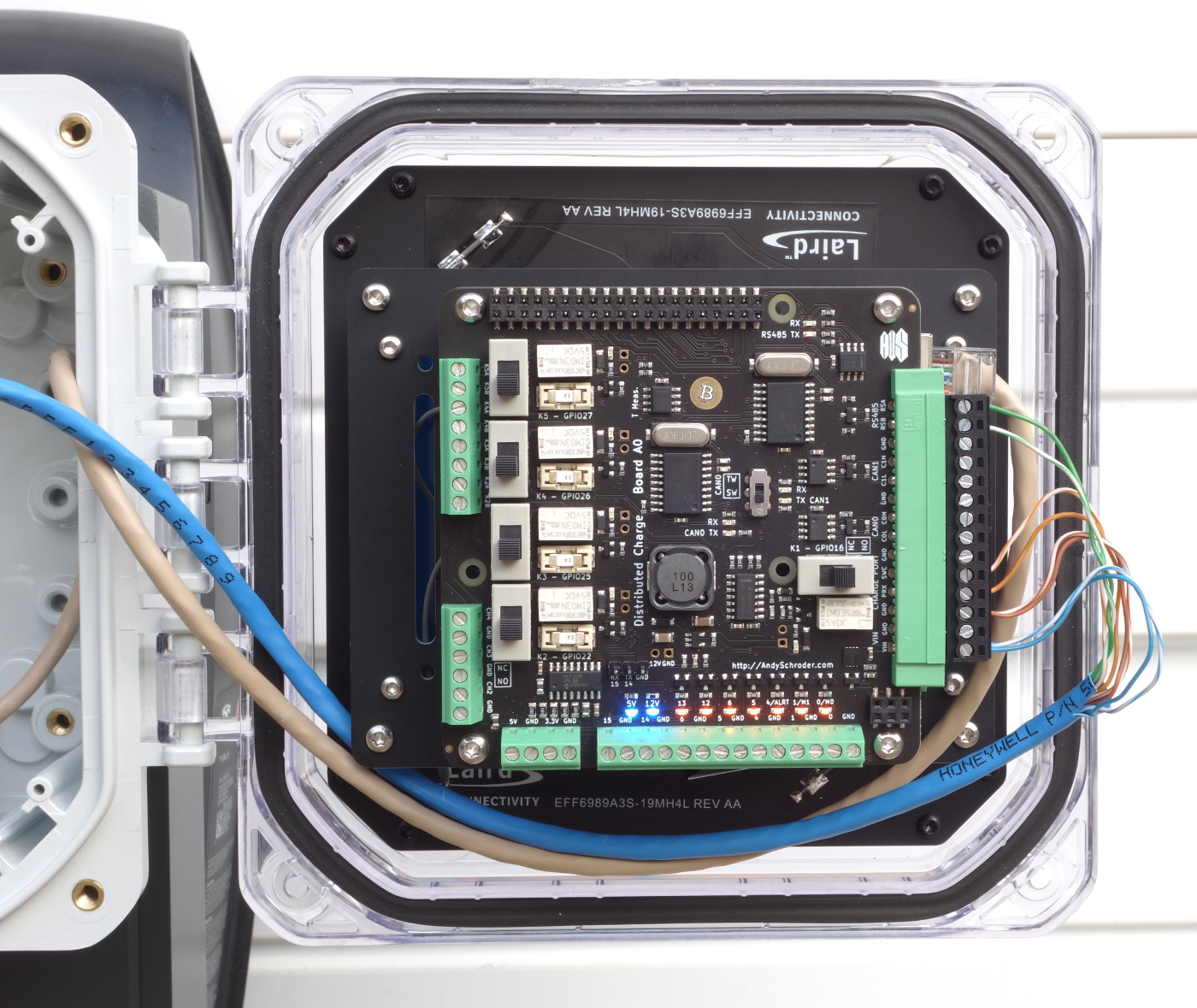
Figure 8: Distributed Charge Board A0 Connection Detail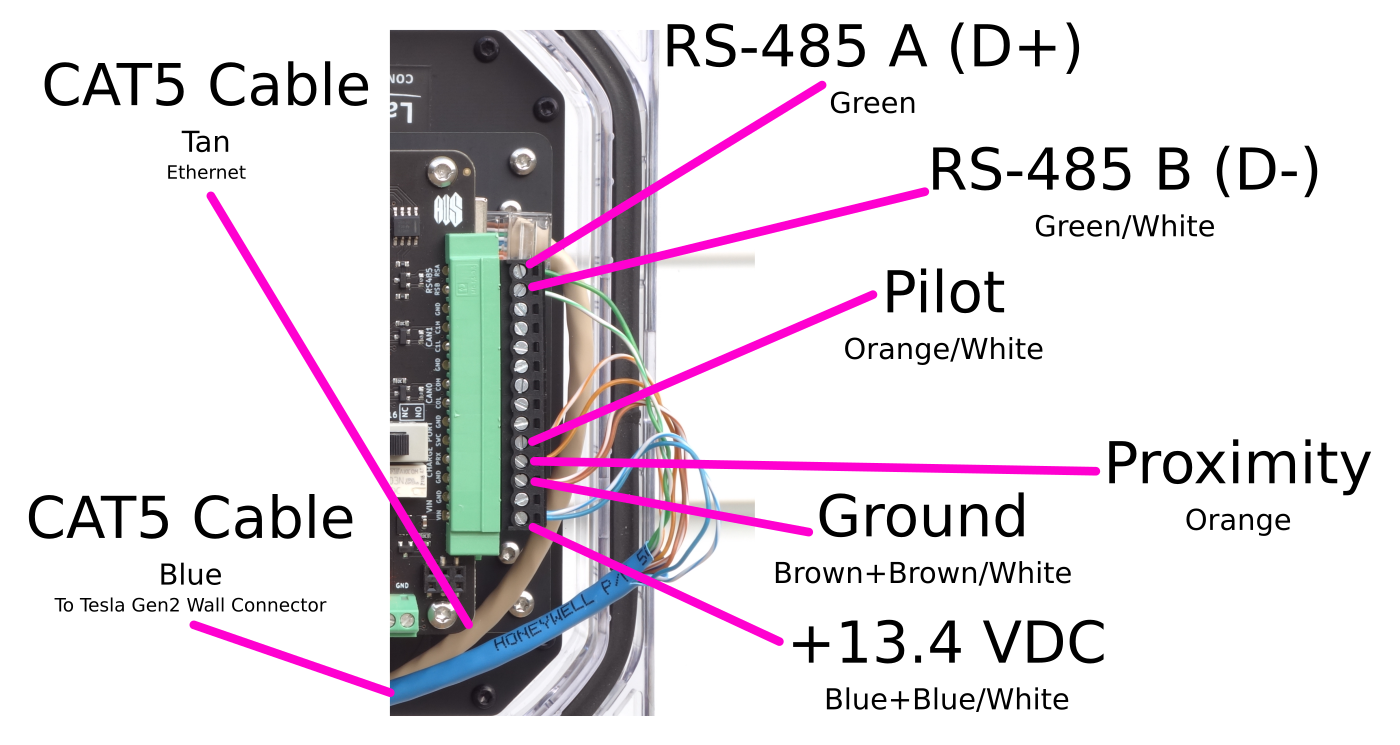
|